
Honda's 150 kW In-Motion Wireless Charging: Resonance, Misalignment, Control, Durability, and Economics
Honda announced a new foundation for dynamic wireless power transfer (D-WPT) on October 5, 2026. At first glance it sounds like a giant wireless charging pad under a highway. The deeper I went, though, the more interesting questions became: how do you keep efficiency high while the magnetic coupling changes continuously, how long can buried power electronics survive, and can the service ever beat the economics of better batteries and faster stationary charging? This article separates what Honda has actually disclosed from my engineering inferences.
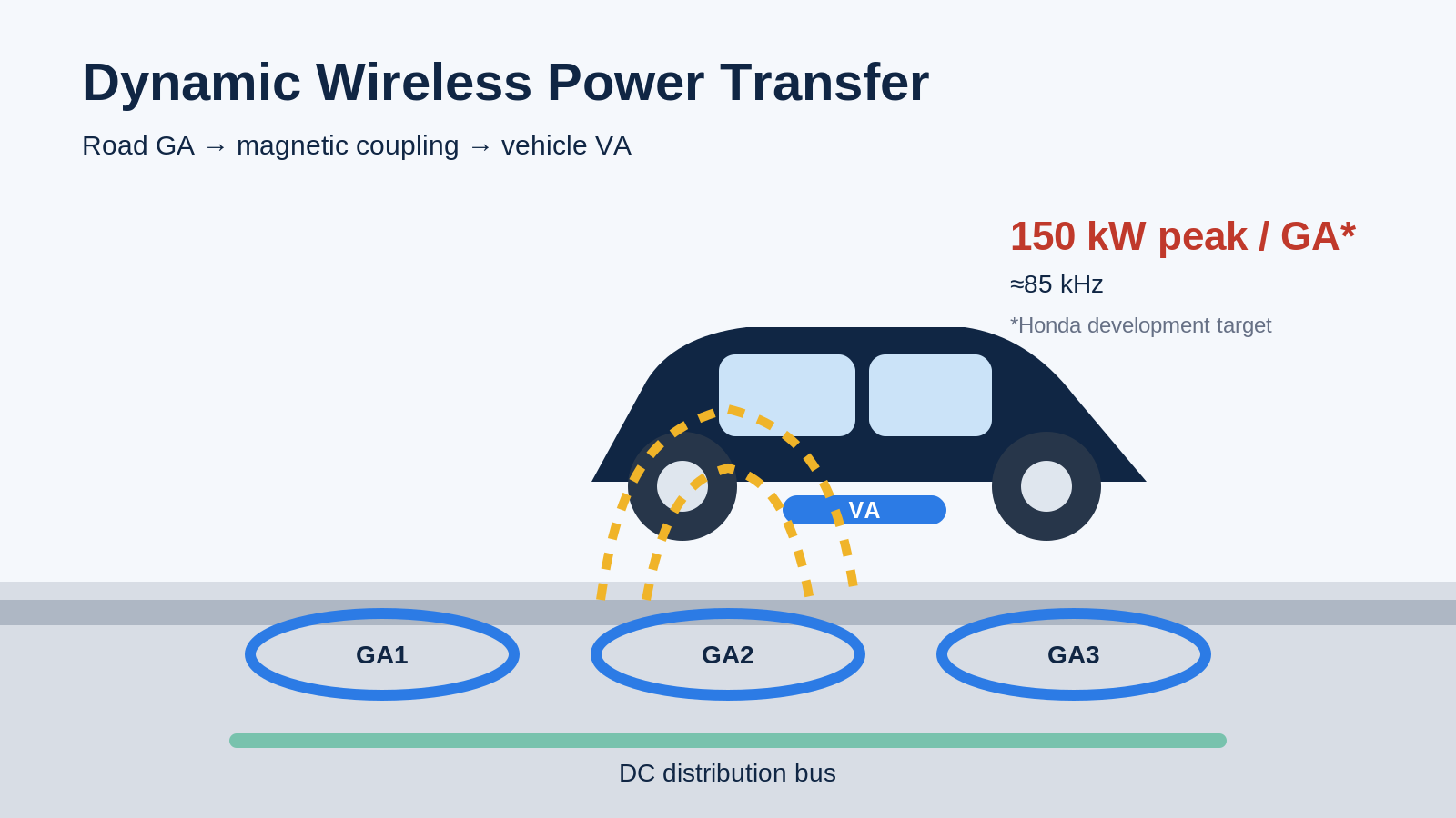
Bottom line first
| What is actually new? | Not magnetic coupling itself. The interesting part is integrating resonance, high-power compact coils, an inverter inside every GA, DC distribution, and road construction. Honda is developing up to 150 kW instantaneous peak transfer per GA. [1] |
|---|---|
| The dynamic challenge | As the vehicle approaches, passes over, and leaves each GA, coupling coefficient k changes continuously. The useful metrics are not only the 150 kW peak but the width of P(x) and η(x): power and efficiency versus position. |
| Efficiency? | Honda has not published its own misalignment-dependent DC-to-DC efficiency map. A separate Purdue/INDOT testbed reports about 85% end-to-end DC-bus efficiency at rated power on an approximately 200 kW roadway, showing that high-power DWPT does not inherently lose half its power. [3] |
| Why one inverter per GA matters | Honda's stated goals are DC distribution, installation/upgrading, and responsive stable power. From a control perspective, the same architecture could also support electrical sensing of coupling and predictive control of the next GA. That part is my engineering inference, not a disclosed Honda implementation. |
| The real blockers | Durability, maintainability, and economics. Honda plans a 1-million-wheel-load test at 49 kN/wheel. A separate Indiana study estimates $3.53–3.65M/mile and 23–31¢/kWh LCOR for its own DWPT assumptions. [2][6] |
| My read | Long-haul heavy trucks make sense as the first target. Passenger cars are a much harder business case because DWPT competes with future cheaper, denser batteries + faster stationary charging. Honda itself says it is developing battery performance in parallel with D-WPT. [1] |
1. What Honda actually announced
Honda, Taisei Corporation, and Taisei Rotec announced underlying technology for a magnetic-coupling in-motion wireless power road. Multiple Ground Assemblies (GAs) are embedded in the road, while a Vehicle Assembly (VA) is mounted under the vehicle. A ground DC supply distributes DC along the road; each GA contains its own inverter to create AC at roughly 85 kHz, which produces the alternating magnetic field received by the VA. [1][2]
Honda uses a circular coil made from thin copper strip rather than conventional bundled litz wire. The design targets compact packaging while managing skin effect at roughly 85 kHz and maintaining the 150 kW peak capability. [1]
2. Magnetic coupling is old; resonance is about making weak coupling usable
An AC current in the transmitter coil creates an alternating magnetic field; the receiver coil converts that field back into electrical current. The basic principle is the same family of physics as a phone's wireless charger. Honda highlights the resonant capacitors on both sides. [1]
A useful clarification: resonance does not magically make the magnetic field wider. Misalignment still reduces coupling. The mutual inductance M and coupling coefficient k are related by: [5]
M = k√(L₁L₂)
L₁ and L₂ are the self-inductances of the transmitter and receiver coils. If k falls with lateral offset or greater air gap, M falls too. Resonant compensation cancels much of the reactive impedance, making it easier to transfer useful real power even when coupling is weaker.
It does not keep k from falling. It can keep lower-k operating points useful. That is why I would like to see Honda publish measured k(x,y,z), P(x,y,z), and η(x,y,z) maps.
3. In motion, the width of the power window matters more than the peak
Static wireless charging can ask the driver to park over the pad. Dynamic charging cannot. For every GA the vehicle goes through approach → alignment → departure. If x is travel direction, y is lateral offset in the lane, and z is the coil gap, coupling becomes a function k(x,y,z).
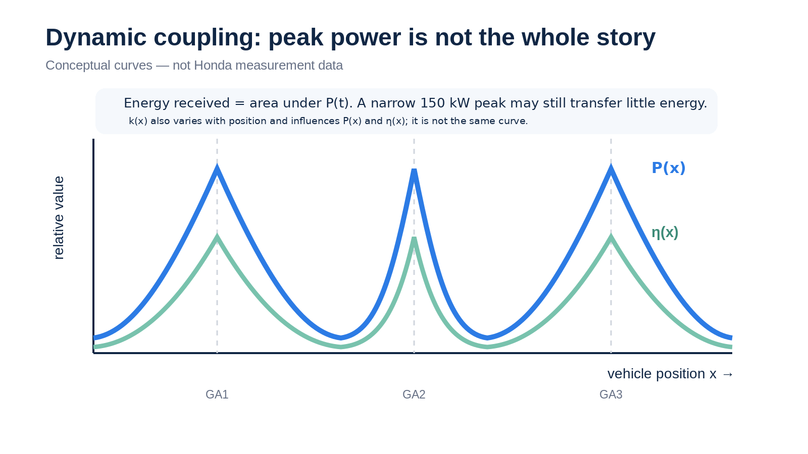
At 100 km/h (62 mph), a vehicle covers 1 km in 36 seconds. If 150 kW could somehow be maintained over that whole kilometer, the energy would be 1.5 kWh:
150 kW × 36 s ÷ 3600 = 1.5 kWh
Real roads have finite GA length and pitch, switching windows, misalignment, and a changing power curve. The actual energy received is the time integral of P(t), i.e. the area under the power curve.
A useful reality check comes from the separate Purdue/INDOT project in the U.S. INDOT currently reports about 85% end-to-end efficiency from roadway inverter DC bus to vehicle DC bus at rated power on its approximately 200 kW testbed, with roughly 10–11 in (25–28 cm) transmitter-to-receiver separation. INDOT says vehicle speed changes the total energy received over a road length, not the instantaneous rated power while the receiver is above an active transmitter. [3]
The 85% result is from Purdue/INDOT's different system. Honda has not yet published a DC-to-DC efficiency map versus lateral offset and gap. But the result is useful evidence that “150 kW wireless means only 50 kW arrives” is not a necessary outcome.
4. One inverter per GA is interesting from a controls perspective
Honda's architecture integrates the inverter and coil inside each GA, then connects GAs with DC distribution. Honda's public rationale is simpler buried wiring, easier installation and renewal, plus responsive and stable high-power delivery when paired with Taisei's DC supply. [1][2]
The next part is engineering inference, not a disclosed Honda control algorithm. When the vehicle receiver approaches, its electrical effect appears at the transmitter as a reflected impedance. In a simple model, if Z₂ is the receiver-side impedance,
Zref = (ωM)² / Z₂
As M and k change, the GA inverter sees changes in voltage, current, and phase. That means the power-transfer circuit itself potentially contains sensing information about coupling.
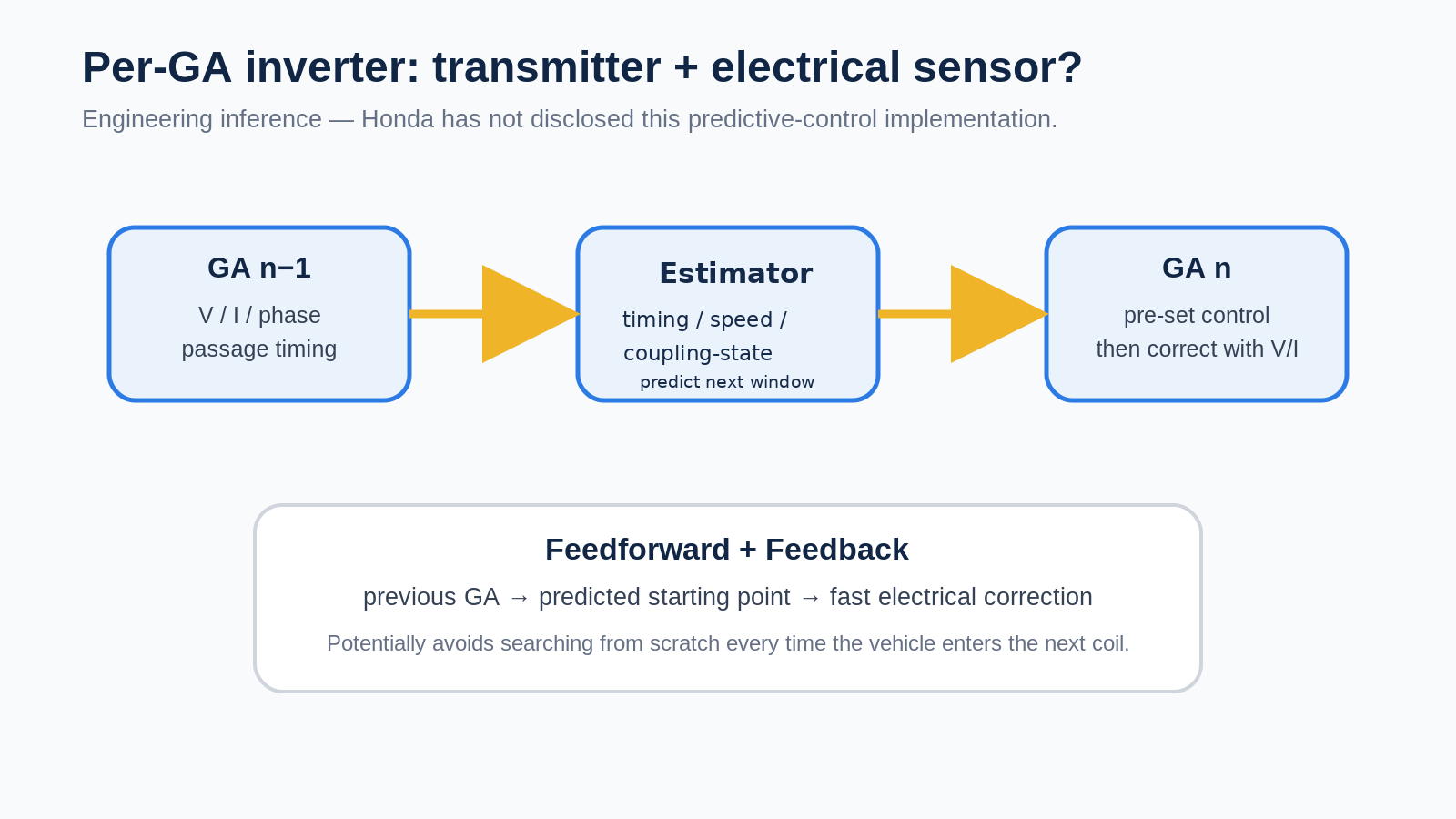
With a chain of GAs, the electrical response from the previous unit could be used to estimate passage timing, speed, and a coupling-state indicator, then anticipate the time window and approximate coupling state at the next GA. Rather than searching from scratch, the next unit could begin near a predicted operating point with feedforward, then correct the residual error from measured V/I with feedback.
That does not mean M or k can necessarily be identified uniquely from V/I/phase alone. Load state and resonant detuning can produce overlapping electrical signatures, so I treat this more cautiously as coupling-state estimation, not direct measurement of M or k.
Sensorless receiver-position detection is not just a thought experiment. In 2026, Lapickis et al. demonstrated a low-power DWPT bench that used changes in inverter input current to detect the receiver and switch transmitter coils without external position sensors. The prototype reached 77 cm/s and 53.8% maximum efficiency, so it is a proof of concept—not evidence that the same method is ready for 150 kW highway use. [4]
What about lateral y-offset?
x changes rapidly and inevitably as the vehicle passes each GA. y may be slower and smaller if the vehicle stays near the lane center, so lateral offset may be less of a fast-control problem. But a sustained 10–20 cm offset over many kilometers could still create a steady efficiency penalty.
In principle, a laterally segmented transmitter array could estimate y from left/right coupling differences. Honda's public material, however, describes a circular GA coil and does not disclose a multi-column lateral array. On a highway, lane centering plus a coil design with sufficient misalignment tolerance may be simpler than a complex 2D array.
5. Maintenance: no moving parts, but the power electronics are buried in the road
D-WPT does not need a mechanically flexing energy harvester like a piezoelectric floor. That removes one class of mechanical fatigue. But Honda's architecture places the inverter inside the buried GA, so heat, water, vibration, heavy axle loads, and future resurfacing become the real infrastructure problem.
Honda says it is applying inverter durability know-how from hybrid-vehicle development, and the GA is designed for milling-and-embedding installation into existing pavement and for future pavement renewal. Starting in late 2026, the partners plan a 1-million-wheel-load durability test at 49 kN per wheel, along with DWPT performance and electromagnetic-leakage testing. [1][2]
The architecture suggests confidence in durability, but long-term road-infrastructure life is exactly what still needs validation. For economics, MTBF is only half the story; MTTR—how quickly one failed GA can be isolated and replaced—matters too.
6. Economics: technically possible is not the same as commercially competitive
This is where the problem becomes much harder. Even stationary 150 kW-class fast charging is not cheap infrastructure. DWPT adds pavement work and distributes power electronics along the road.
I used Houston gasoline prices plus our real-world Nissan Ariya and Mazda CX-9 efficiency to compare home charging and public DC fast charging in $/100 miles. It is useful context for D-WPT economics because the EV advantage changes dramatically depending on where and how the vehicle is charged.
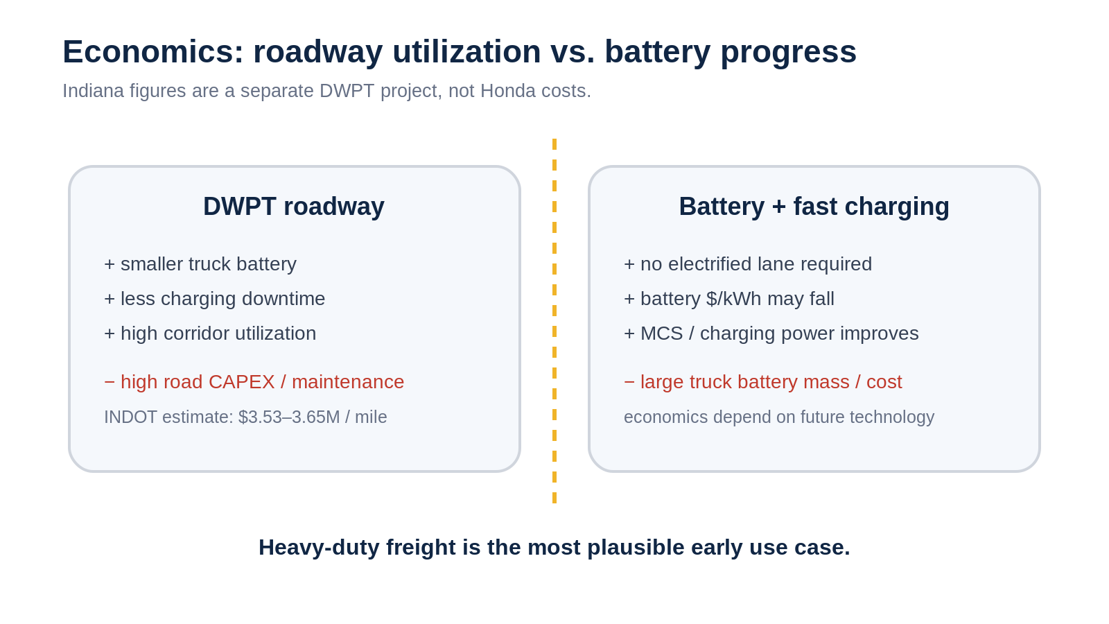
In a separate 2025 Indiana presentation, the estimated capital cost for DWPT on Indiana Interstates was $3.53–3.65 million per mile, with a Levelized Cost of Roadway (LCOR) of 23–31¢/kWh. The same slide used 32¢/kWh as an estimated fleet-operator TCO breakeven electricity price versus diesel. These are not Honda costs; they are scenario-based figures for the Indiana project. [6]
The reason a very expensive road can still have a business case is utilization. A freight corridor can sell huge lifetime energy throughput to vehicle after vehicle. An Energy Policy analysis of Indiana electric roads found that EV penetration—especially heavy-duty long-haul EV adoption—has one of the largest effects on financial viability. [7]
For heavy trucks, DWPT can also reduce the battery required for a long route, lowering mass, purchase cost, and replacement cost while preserving payload and reducing charging stops. A 2025 long-haul freight techno-economic study models exactly those benefits and also finds high charging-infrastructure utilization important to cost parity. [8]
The real competitor may be future batteries + MCS
This is my interpretation. DWPT creates value when the battery cost/weight and avoided charging downtime are worth more than the roadway CAPEX and maintenance. If battery $/kWh falls sharply, energy density and life improve, and Megawatt Charging Systems let trucks recover enough energy during mandatory breaks, the relative value of electrifying the road falls.
The long-haul study explicitly discusses MCS as a competing infrastructure path and includes future battery-cost reductions in its scenarios. [8] Honda also says it is pursuing battery-performance improvements in parallel with D-WPT rather than treating the road as the only solution. [1]
| Use case | My current read | Why |
|---|---|---|
| Long-haul heavy trucks | Most plausible | High utilization; large value from smaller batteries, payload, and less charging downtime. |
| Fixed-route buses / ports / logistics hubs | Promising | Predictable routes and high infrastructure utilization. |
| Passenger-car highways | Harder case | Home charging is cheap; batteries and ultra-fast charging are improving; roadway CAPEX needs very high utilization. |
7. Conclusion: the numbers I want are efficiency × life × utilization
The headline number is “150 kW while driving,” but the system becomes much more interesting when you look behind it.
- Magnetic coupling itself is mature; the challenge is integrating resonance, power density, compact hardware, DC distribution, and pavement construction.
- Because k changes continuously in motion, P(x) and η(x) matter more than a single peak-power number.
- Per-GA inverters are officially about installation and responsive power delivery, but the architecture also looks friendly to sensorless estimation and predictive control.
- Burying the inverter is bold; durability and replacement time are still to be proven at road scale.
- Heavy-freight utilization can create an economic case, but passenger cars face strong competition from future batteries and faster stationary charging.
The next Honda data I most want to see are measured k(x,y,z), P(x,y,z), η(x,y,z), plus GA replacement and lifetime data. Those will tell us whether this is only impressive engineering or a genuinely scalable charging service.
Technical Note: one level deeper into the equations
Symbols
- L₁, L₂: transmitter/receiver self-inductance
- M: mutual inductance
- k: coupling coefficient
- ω: angular frequency (2πf)
- R₁, R₂: transmitter/receiver loss resistance
- RL: equivalent AC-side load representing rectifier/DC-DC/battery behavior
- Q: resonator quality factor
Coupling
M = k√(L₁L₂)
More offset or gap generally reduces k and therefore M.
Reflected impedance
Zref = (ωM)² / Z₂
The receiver appears as an additional impedance at the transmitter. Conceptually, Zin = Z₁ + Zref. Near resonance, changes in M² can show up strongly in the GA's electrical measurements.
Unloaded and loaded Q
Q₀ = ωL / R
Qloaded = ωL / (R + Req)
The coil's unloaded Q can be relatively fixed, while loaded Q changes with the coupled load and reflected impedance.
Figure of merit and maximum link efficiency
FoM = k√(Q₁Q₂)
g = k²Q₁Q₂
ηmax = g / (1 + √(1+g))²
In a simplified two-coil resonant model, k and Q strongly bound the achievable link efficiency. [5]
SS vs. LCC compensation
SS (Series-Series) uses series compensation capacitors on both transmitter and receiver. LCC adds another L/C network to gain more freedom over current-source behavior and load variation. Honda discloses resonant capacitors but has not publicly identified the exact SS/LCC compensation topology in the material used here.
Could a probe signal identify the state?
In principle, a small perturbation and Z(jω) measurement can help separate M, load, and detuning. In a real high-power inverter, however, the operating-frequency neighborhood contains PWM sidebands, dead-time effects, control-loop action, EMI, and ADC dynamic-range limitations. So probe-frequency selection is a system-identification problem, not a free measurement channel. Existing V/I signatures or naturally occurring harmonics may be more attractive; Honda's implementation is undisclosed.
What is Honda data vs. my inference?
- Honda disclosed: ≈85 kHz, 150 kW instantaneous peak/GA, circular copper-strip coil, per-GA integrated inverter, DC connection, installation/upgrading goals, high-response DC supply, million-wheel-load testing, Tateyama demo, and heavy-duty logistics as the initial target.
- Separate-project benchmarks: Purdue/INDOT ≈85% testbed efficiency and ≈200 kW roadway; Indiana cost/LCOR estimates.
- My engineering inference: passing state estimates from one GA to the next, predicting k(t), feedforward + feedback, y/z estimation, and probe/harmonic system identification.
References
- Honda, Honda technology feature: Dynamic Wireless Power Transfer (Japanese, Oct. 5, 2026).
- Honda, Honda Develops Underlaying Technology for In-motion Wireless Charging of EVs, Including Large Commercial Vehicles (Oct. 5, 2026).
- Indiana Department of Transportation (INDOT), Dynamic Wireless Power Transfer project / FAQ (accessed Oct. 6, 2026).
- Lapickis, D., Stepins, D., Zakis, J., Dynamic Wireless Power Transfer System Without Receiving Coil Position Detection Sensors, Electronics 15(4), 756 (2026).
- Yang, Y. et al., Design Methodology, Modeling, and Comparative Study of Wireless Power Transfer Systems for Electric Vehicles, Energies 11(7), 1716 (2018).
- INDOT / Purdue, Dynamic Wireless Power Transfer — Presentation (July 30, 2025).
- Haddad, D. et al., Analysis of the financial viability of high-powered electric roadways: A case study for the state of Indiana, Energy Policy 171, 113275 (2022).
- Costantino, T., Miretti, F., Spessa, E., Assessing the viability of dynamic wireless power transfer in long-haul freight transport: A techno-economic analysis from fleet operators’ standpoint, Applied Energy 379, 124839 (2025).
Questions or comments?
If you want to go deeper on resonance, misalignment, reflected impedance, road durability, or the economics, send me a note.
This article grew out of a thread where one question kept producing another: resonance, misalignment, per-GA inverters, sensorless control, maintenance, then economics.